What do you know about designing roof drainage systems?

It’s just gutters and downpipes…isn’t it?
Well, for the most part, yes, but what about developing a suitable layout, being able to size everything and getting the specifications right?
As an early-career architect, you may have been tasked with designing the rainwater drainage on a small to medium-sized project. It’s a typical task because it appears to be a relatively straightforward thing to do.
However, the guidance on the subject isn’t great, and the regulations can be confusing. This can result in misunderstandings, even for a simple subject like this.
This post provides some background explanations and attempts to clarify some of the most common issues. It’s limited to roofs with conventional eaves arrangements where the gutters will overspill if the drainage capacity is overcome without causing water damage.
The tables in Approved Document H
If you’ve already been asked to calculate gutter and downpipe sizes for a project, and you’re working in England or Wales, you’ll probably be aware of the following tables:
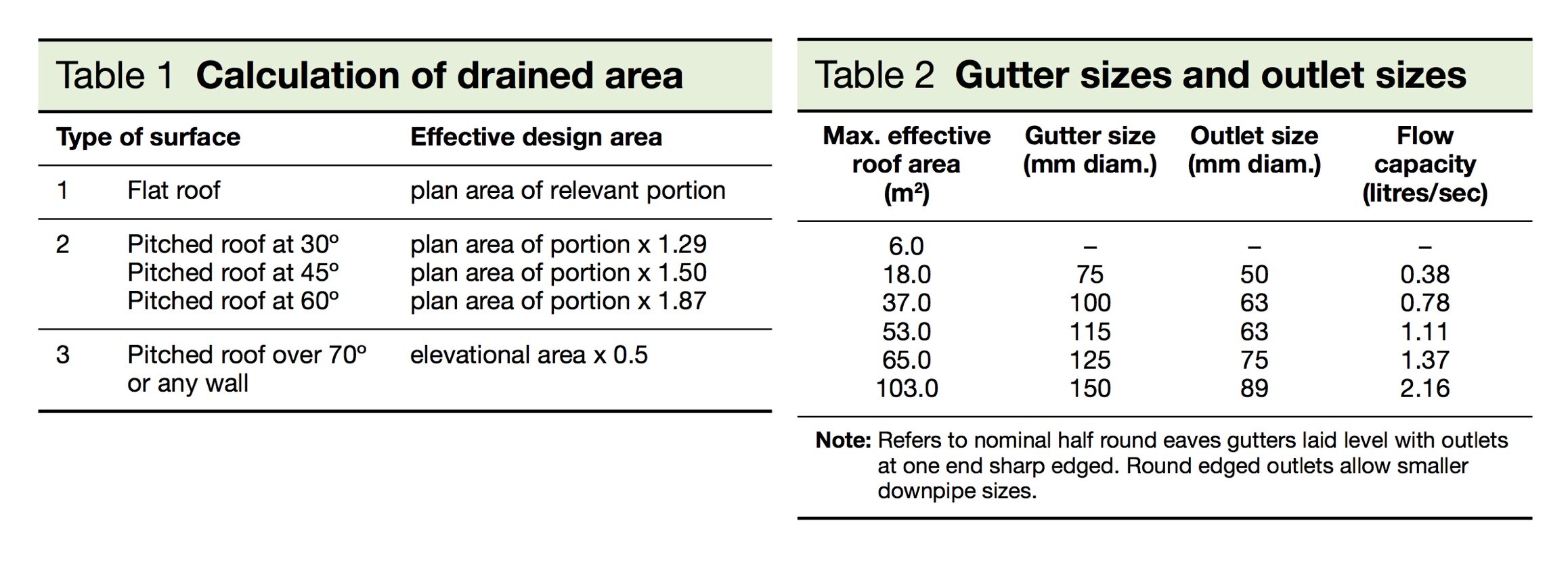
Tables 1 and 2 from Section H3 of Approved Document H (2015 for use in England) to the UK Building Regulations
Table 1 gives a method of calculating ‘effective design areas’ without explaining why they’re necessary or how they’re derived. Table 2 gives ‘maximum effective roof areas’ for common gutter and outlet sizes, also without explanation. The note states the circumstances in which the information in the table applies but doesn’t explain what to do otherwise. Also, knowing what to do with the flow capacity information is a bit of a mystery.
This is fairly typical of the Approved Documents. They’re helpful up to a point but because there’s no room for explanation, they also beg many questions. Sometimes, they can also be confusing.
So here’s some basics.
Purpose of rainwater drainage
The purpose of a rainwater drainage system is to collect and channel rainwater falling on a building to an underground surface water drainage system so that the rainwater doesn’t cause damage to the building.
The calculation of gutter and downpipe sizes involves assessing the quantity of rain falling on the building as well as assessing the capacity of the rainwater drainage system to cope with that rainfall. Before getting into the details, it will be worth obtaining a sense of the relative scale of the problem by looking at a few different building types.
Dwellings

Photo by Lina Kivaka from Pexels
About 25 million homes in the UK, of which 80% are detached, semi-detached or terraced houses. A tiny proportion of these houses have flat roofs, which means that approximately 20 million homes have pitched roofs with conventional eaves arrangements. Hence, this is, by far, the most common roof drainage situation.
For most dwellings, you’ll find that gutters range in size from approximately 100mm diameter to 150mm diameter (assuming gutters with a ‘half-round’ section profile), and downpipes range from approximately 60mm diameter to 90mm diameter (assuming circular downpipes). One way of estimating the sizes of gutters and downpipes would be to find an existing building of similar size in the same location with a similar roof arrangement and adopt the same sizes. Assuming, of course, that there is no evidence of damage to the building from rainwater.
Understanding this way would be useful before carrying out any detailed calculations. It would help to make sure that you avoid any significant errors, and it would help you to derive an approximate solution.
Small buildings
For small buildings, such as domestic outbuildings or cabins of various kinds, there will be a point at which the quantity of rain falling on the building is so small that it means that the provision of gutters and downpipes is uneconomical. In these instances, do the regulations require you to provide a rainwater drainage system?
If you look at Table 2 above, you will see that the line for an effective roof area of 6sqm has a series of blanks. This implies (without explicitly stating), that if your effective roof area is 6sqm or less, then you don’t need to provide a rainwater drainage system.
The figure of 6sqm comes from earlier guidance in British Standards (now superseded) that stated that roofs having an area of 6sqm or less, do not need gutters and downpipes. There’s a difference between ‘roof area’ and ‘effective roof area’, so the two references don’t quite match. However, the figure of 6sqm is a somewhat arbitrary cut-off and there are things, other than size, that also need to be considered.
For example, the function and importance of the building, the form of the roof and the ability of the eaves to shed water clear of the building if there are no gutters.
At this scale of building, there is some subjectivity, and you will need to form your own view and agree your approach with Building Control (assuming that your small building forms part of a proposal that requires Building Regulation approval).
Large warehouses

Photo by Scott Webb on Unsplash
Let’s say you are designing a large distribution warehouse for an online book retailer. The size of the building and the requirement for a slick appearance lead to a solution where the entire roof drainage system has to be concealed. This results in using internal parapet gutters, internal valley gutters and internal downpipes. In this situation, failure of any part of the roof drainage system could lead to water penetration inside the building, which could, in turn, lead to serious damage to both the building and its stock.
This is an example where the risk of failure, and the consequence of failure, is more severe than for a dwelling with a conventional eaves arrangement. A significant safety factor must be included in assessing the rainwater drainage system.
In practice, the margin of safety is achieved by considering storm events of much higher rainfall intensity. The Approved Document refers to the relevant British Standard (BS EN 12056-3: 2000), which considers different circumstances based on the anticipated life of the building and the risk of failure.
If the building had been a remote archive storing priceless manuscripts for the British Library, the design life would have been longer, and the risk of failure would have been higher than for a distribution warehouse. The design rainfall intensity adopted would, therefore, be correspondingly higher.
The most important things to appreciate are the level of risk for your situation and the consequences of drainage failure.
Some background to the calculation of rainwater drainage
Although the solution to rainwater drainage, i.e. gutters and downpipes, has existed for thousands of years, our ability to reliably predict adequate sizes by calculation is a relatively recent development. This is because the mathematics associated with the subject is complex and relies on physical testing.
The Building Research Station (now known as the Building Research Establishment or BRE) began carrying out tests of drainage systems during the post-war period. This led to the publication of reference documents and eventually to a series of design standards culminating in the current standard, BS EN 12056-3: 2000.
During the development of these standards, the Approved Documents to the Building Regulations were also developed. The current version of Approved Document H: Drainage and Waste Disposal relies heavily on references to BS EN 12056-3: 2000, but it also contains information from earlier standards, which are meant to have been superseded. This is one source of potential confusion.
It is also worth noting that BS EN 12056-3: 2000 is a ‘European Standard’, which means that it is written to accommodate all the countries of the European Union, even though these countries may have different procedures. This is another source of potential confusion.
The Approved Document is a mix of current and previous guidance, the latter being included because it simplifies in certain circumstances. A safe and consistent approach would be to follow the guidance of BS EN 12056-3: 2000, but the alternative methods in the Approved Document (such as Tables 1 and 2) also remain valid.
Rainfall intensity
Knowing the rate at which rain falls on your roof is vital in assessing the rainwater drainage capacity. This rainfall rate is known as the ‘rainfall intensity’ and was previously measured in a unit of ‘mm/hour’. Before the introduction of BS EN 12056-3: 2000, a rainfall intensity of ‘75mm/hour’ was used for design purposes in most situations. The exception was where the risk of rainwater drainage failure was higher than usual.
Rainfall intensity is now measured in ‘litres/second/square metre’ (l/s/sqm), and rainfall intensity values are given for different geographic areas of the country. For eaves gutters, the rainfall intensity is provided in a map of England & Wales shown in Diagram 1 of Section H3 of Approved Document H. The l/s/sqm figures range from 0.016 to 0.022. It is worth noting that 75mm/hour is equivalent to 0.021l/s/sqm.

Looking at the map, you may be surprised that the highest rainfall intensities do not occur in regions known for the highest annual rainfall (Wales and the North) and occur in the East and South East of England. This is because the highest rainfall intensities occur during summer thunderstorms, which are more severe in regions with higher temperatures.
The rainfall intensities were assessed from meteorological data collected over 40 years ago, and it could be argued that there is a need for this to be reviewed, given recent changes to the UK climate.
Explanation of Table 1
The catchment area of a gutter or downpipe should be assessed by looking at the geometry of the roofs shedding water into the system. The total quantity of rain flowing into the system is simply the rainfall intensity multiplied by the relevant catchment area (i.e. the amount of rain per square meter multiplied by the number of square meters).
Flat roofs:
In the case of flat roofs, the catchment area is the same as the footprint area of the roof being drained. This applies to rain falling vertically or at an angle when blown by the wind.
Pitched roofs:
For pitched roofs, the catchment area would be the same as the footprint area of the drained roof for rain falling vertically. But for rain falling at an angle - when blown by the wind - the catchment area will be larger than the footprint area of the roof.
The design methods in both the Approved Document and British Standard require wind-driven rain to be assumed. For design purposes, they assume that the rain falls at an angle of 2:1 or approximately 26 degrees from vertical. This geometry was adopted because the catchment can be calculated as an ‘effective area’ on the horizontal plane by adding the footprint area and half of the elevation area together.

Calculation of effective area for a pitched roof
The British Standard states that the effective area should be calculated using the method of adding the roof footprint area to half of the elevational area of the roof (because of the assumption that the rain is falling at an angle of 2:1). As well as being simple, this approach also has the advantage of working for all values of roof pitch, including steep roofs up to 90 degrees, when the roof becomes a wall.
In Table 1 (above), the Approved Document gives multipliers for roof pitches of 30, 45 and 60 degrees for calculating effective area. These are based on trigonometry (i.e. the multiplier = 1+tan(roof pitch)/2) and can be calculated for any roof angle. However, because the ‘tan function’ tends towards infinity as the angle approaches 90 degrees, this approach doesn’t work well for steeper roof pitches. Hence, the Approved Document states that the effective area should be half of the roof's elevational area for pitches above 70 degrees.
Both approaches are valid, but the British Standard is more consistent.
Complex roofs:
In more complex roof forms, for example, where one roof slope drains onto another, the total effective area is simply the sum of the individual effective areas in question.
If a roof abuts a wall, the wind-driven rain falling against the wall should also be added to the effective area based on half of the wall area (up to a maximum wall height of 10m).
Explanation of Table 2
The use of Table 2 is limited to true half-round gutters that are short, laid nominally level and with ‘sharp-edged outlets’. It is an amalgamation of Tables 1 and 5 from an earlier British Standard (which has been superseded) and uses the historic rainfall intensity of 75mm/hour (which has also been superseded) rather than the rainfall intensities in the map of Diagram 1.
Why would such out-of-date information be included in the current Approved Document? Because it’s simple and works and applies to the 20 million homes with conventional eaves arrangements.
However, it is also confusing, so here’s some additional explanation:
Table 2 is limited to true half-round gutters, but for domestic-sized gutters, it will also give reasonably good answers for nominally round and rectangular gutters of the same cross-sectional area.
A short gutter is defined as less than 50 times the water depth (i.e. 50 times the radius of a true half-round gutter). A 100mm diameter gutter is only ‘short’ up to 2.5m in length. Longer gutters can be used, but the gutter capacity must be reduced for frictional effects. Clause 5.1.6 and Table 6 of BS EN 12056-3: 2000 provides a method.
A gutter ‘laid nominally level’ means a gutter laid to a shallow fall of a maximum of 3mm/m but designed as if it were level. Installing the gutter to a slight fall is done to overcome construction inaccuracies and any potential settlement. Although gutters laid to a steeper fall have greater capacity, in the case of eaves gutters, this is generally not done because of the visual consequences.
A sharp-edged outlet is one formed by the intersection of the cylindrical downpipe connection and the half-round gutter. It is distinct from round-edged or tapered outlets, which allow greater flow and, therefore, higher capacities.
The Approved Document doesn’t mention that if the gutter changes angle on plan, its capacity should be reduced.
No use is made of the flow capacities stated in Table 2. However, they can be used to confirm that the rainfall intensity used was 0.021l/s/sqm (i.e. 75mm/hour). Simply divide the flow capacity by the corresponding effective area.
Clause 1.1 of The Approved Document states that the rainfall intensities in Figure 1 can be used for eaves gutters and downpipes, but a) it doesn’t state what to do with them, and b) it doesn’t use them in Table 2.
Photo by Adrien Olichon from Pexels
Design Approach
For a given roof configuration, the first task is to decide on the number and location of downpipes, as this will determine the size of the effective roof areas.
In many instances (though not necessarily always), you will want the gutter and downpipe sizes to be the same for all gutters and downpipes on the project. This means that it will be beneficial if the various catchment areas are similar. The sizing need only be carried out for the most critical case.
If possible, you should avoid a situation where the critical case is much more onerous than the rest, as this will result in an uneconomic installation.
Having established a first layout, you can assess the gutter and outlet sizes using Table 2 or via your own calculations based on the rainfall intensity map and the calculations given in BS EN 12056-3: 2000. I have developed a spreadsheet which provides maximum effective areas for nominally level 100mm and 150mm diameter true half-round gutters and lengths up to 10m. It provides more detailed information than Table 2 of the Approved Document and therefore permits more economical solutions. It could be further developed for other gutter sizes and shapes.
Having established an approximate solution, you can then obtain actual gutter and outlet capacities from the manufacturer of the system you have chosen. With this information, you can check your previous calculations and ask the manufacturer also to carry out their own calculations.
That sounds like a lot of work. Why not ask the manufacturer to do all of the work for you and leave it at that?
The manufacturer will usually be happy to do the necessary calculations, as they’ll be keen to sell their products. However, they won’t take design responsibility for it and their output will contain disclaimers to that effect. You are the architect, and therefore you are responsible for the design. So you really need to understand what you’re doing.
The approach outlined above means that you develop your own approximate solution, which is then refined and, effectively, checked by the manufacturer. In this way, you gain confidence in your own work while also confirming that the manufacturer isn’t oversizing things.
Conclusions
The subject of rainwater drainage is a typical aspect of building design - it is relatively simple, but it can also be confusing. It has developed over time, and current methods and recommendations overlap with those of previous years.
Here are some things to bear in mind:
- The regulations don’t provide explanations, so you really need to understand what you’re doing before you start using them.
- I have provided a list of useful references (see below), including some text books where roof drainage is covered. Be aware of the publication dates of references relative to the dates of current regulations.
- The information in this post refers to eaves gutters only. Parapet and valley gutters are treated differently because they have a higher risk of failure.
- Working with manufacturers will help develop your understanding, but don’t delegate your design responsibility to them.
- On larger and more complex schemes, specialist consultants may be employed to design the rainwater drainage system. This will be another opportunity to develop your understanding. Take advantage of it.
To help you develop your expertise further, in future posts, I’ll provide a range of worked examples and look at valley and parapet gutter situations.
Note: In developing the post, I’ve referred to relevant guidance, textbooks and trade literature, a summary of which can be found here.